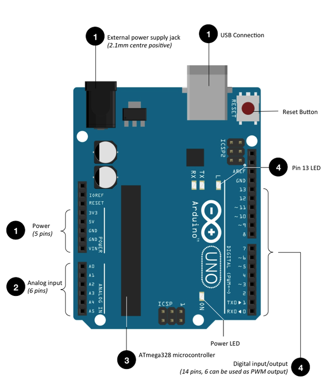
I. Arduino Board
|
1. Power
2. Analog Input
3. Memory
4. Digital Input/Output
|
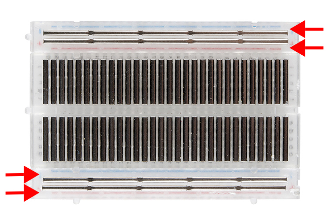
II. Breadboard
A breadboard is used to connect components to form circuits. No *soldering is required so it is easy to change connections or replace components.
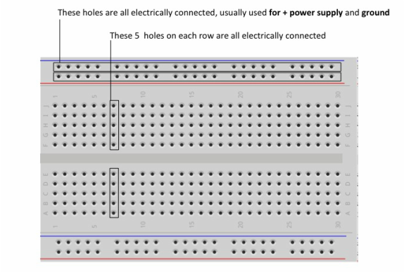
* Soldering: a technique to join 2 conductive (metal) contacts in a circuit
III. Beginner's Electronics
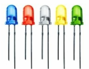
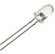
LED (Light Emitting Diode)
Lights up when current flows from the (+) anode, longer lead, to (-) cathode. Requires resistor to limit the current |
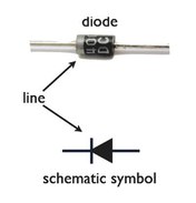
Diode
A device which allows current to flow in only one direction, and prevents the flow of current from the opposite direction |
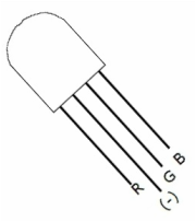
Tri-colour LED
Similar to 3 LEDs of different colours wired together. This is COMMON CATHODE type and its connected to GND. Note the positions of the leads and its corresponding colours |
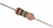
Resistor
Restricts the amount of current that flows through it. The colour bands indicate resistance and tolerance |
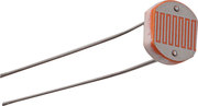
LDR (Light Dependent Resistor) or Photoresistor
Its resistance varies depending on the amount of light |
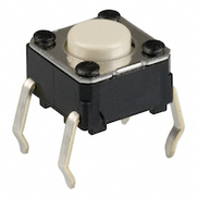
Push Button
A switch - makes contact when the button is pressed |
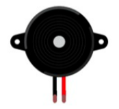
Speaker/Piezo Buzzer
Produces sound in response to an electrical audio signal input |
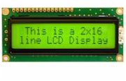
LCD (Liquid Crystal Display)
Displays alphanumeric characters based in digital input signal. It can display 16 characters over 2 lines |
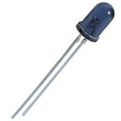
IR LED (Infra-red LED)
Similar to LED but the light is not visible. Infra-red is like heat, not visible to the naked eye. The longer lead is (+) anode |
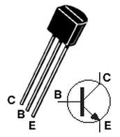
IR Phototransistor
A transistor which current depends on the amount of IR light. The longer lead is the EMITTER. This component is tinted black to prevent interference from visible light |
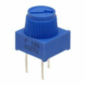
Potentiometer
A simple knob that provides a variable resistance, which we can read into the Arduino board as an analog value |
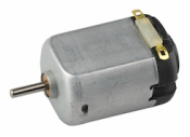
DC Motor
A motor in which speed can be varied by changing the operating voltage or the strength of the magnetic field |
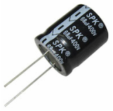
Capacitor
Stores electrical charge - used in timer circuits to smooth power fluctuation and to block direct current (DC) |
Servo Motor
A motor in which the angular position of the shaft is determined by the duration of pulses (PWM signal) to the control terminal |
Transistor
A device which can behave either as a switch or an amplifier. It acts as a switch or amplify electronic or electric signals |
|
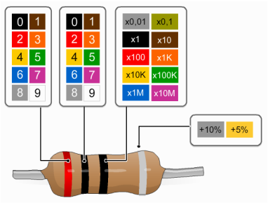
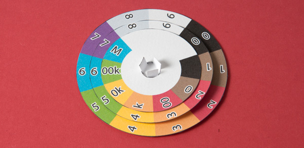
IV. Colours on Resistors
Reading colour bands of any resistor is easy.
For most resistors, there are 4 coloured bands. The 1st & 2nd bands indicate the digits while the 3rd band indicate # of zeros and the last (4th) band indicate its tolerance. For simplicity, we shall ignore the 4th band.
For most resistors, there are 4 coloured bands. The 1st & 2nd bands indicate the digits while the 3rd band indicate # of zeros and the last (4th) band indicate its tolerance. For simplicity, we shall ignore the 4th band.
|
Example
In the diagram given, the order of the colour bands is as follows: 1st: Red (2) 2nd: Black (0) 3rd: Black (x1) Resistor Value: 20Ω More Examples Solve the resistor values of these coloured bands:
|
V. Sketch Structure
The sketch on the Arduino App works on a simplified C Programming language. It consists of 3 main parts namely:
- Declaration: declaring your libraries, variables and data types
- Preparation: Initialise the program once
- Execution: Run the program continuously, unless otherwise specified
Preparation void setup () {
Execution void loop () {
|
Example
Declaration
Preparation void loop () {
Execution void loop () {
|
VI. Definitions of sketch structure
|
1. Basic
|
3. Syntax
|
|
setup( )
To initialise variables, pin modes, start using libraries, etc. This function will only run once, after each power or rest of the Arduino board loop( ) Does precisely what its name suggest, and loops consecutively, allowing your sketch to change and respond. Comes after creating a setup( ) function 2. Pin State
INPUT | OUTPUT
Alters the electrical behaviour of the pin. Used with the pinMode( ) command INPUT: Useful for reading a sensor, or sending in a signal to the Arduino OUTPUT: Useful to powering LEDs, or sending out a signal to a component HIGH | LOW Writing or Reading a value to a digital pin, with varying behaviours when pin is declared as an input or an output a) HIGH (w INPUT) - read with the digitalRead( ) command - reports if a voltage of 3V or more is present at pin b) HIGH (w OUTPUT) - write with the digitalWrite( ) command - reports a voltage of 3V or more to a component c) LOW (w INPUT) - reads with the digitalRead( ) command - report LOW if a voltage of 2V or less is present at the pin d) LOW (w OUTPUT) - writes with the digitalWrite( ) command - reports a voltage of 0V to sink current e.g. to light up an LED that is connected in series with a resistor and +5V. |
// (single line comment)
Comments are lines in the sketch that are used to inform yourself or others about the way the program works. They are ignored by the computer ; (semicolon) Used to end a statement { } (curly braces) To contain your program lines as a whole part under setup( ) and loop( ) functions. Every time you open a brace '{', close it at the end '}' 4. Data Types
int: primary data type of storing integers. e.g. 3, 24. -25
const int: stores a constant integer value. e.g. ledPin = 3, tonePin = 5 float: stores values which has a decimal point. e.g. 3.13, 2.0 char: stores a character value. e.g. 'A', "ABC" void: is a keyword used only in function declaration. e.g. void loop() 5. Library
Coming Soon!
|
VII. Useful Commands
Commands in sketch is very useful and easy to understand. Here, we shall explore 2 different categories of commands:
- Function, and
- Control
1. Function
|
Digital
pinMode (pin, mode)
Configure a pin either an INPUT or OUTPUT mode. "pin" is the pin number between 0 and 19 (digital input/output ranges 0 - 13, while analog input ranges A0 - A5) digitalWrite (pin, value) Once a pin is configured as an OUTPUT, its value can be set either HIGH (+5V) or LOW (ground) digitalRead (pin) Reads the value from a specified pin, either HIGH or LOW tone (pin, frequency, duration) Produces an ON/OFF signal (or a note) very much like the PWM signal. However unlike the PWM signal which repeats itself at a fixed interval, the interval for tone signal is not fixed. Note that the frequency is in Hertz (Hz) and duration in millisecond (ms) |
Analog
analogWrite (pin, value)
Pin 3, 5, 6, 9, 10 and 11 support PWM (Pulse Width Modulation), a kind of rapid ON and OFF signal that simulates analog signal. At a value of 0, the signal is completely OFF while a value of 255, the signal is completely ON 
analogRead (pin)
Reads the value from a specified analog INPUT pin. The value ranges from 0 to 1023, corresponding to input voltages between 0 to 5V |
2. Control
|
if (condition)
{ } This will execute the codes between the curly brackets if condition is TRUE if (condition) {action a} else {action b} This will execute action a if condition is TRUE, else action b is executed for (int x = 0; x < 10; x++) { } Used to repeat a block of codes a number of times. In this case x is initialised with 0, and will be incremented (can be decremented as well using x--) as long as x < 10. As a result, the block of codes within the curly brackets will be repeated 10 times |
|
VIII. References & Links
Texts
Stores
Helpful Links
- Chumbaka
- Arduino Companion (Apple Store)
Stores
Helpful Links
- Fritzing
- Resistor Code Calculator (Apple Store)
- Resistor Wheel (From AdaFruit)
|
| ||||
