You will design a night light which automatically turns on when it senses darkness.
Software Discovery: Analog input, Serial Monitor
Other Discovery: LDR, Resistance
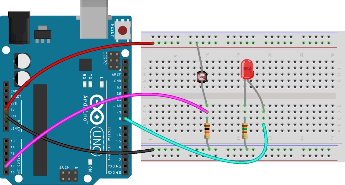
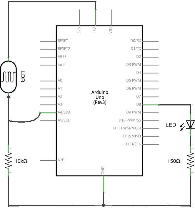
Qty Part
1 LED
1 Photoresistor (LDR)
1 Resistor [150Ω]
1 Resistor [10 kΩ]
Software Discovery: Analog input, Serial Monitor
Other Discovery: LDR, Resistance
Qty Part
1 LED
1 Photoresistor (LDR)
1 Resistor [150Ω]
1 Resistor [10 kΩ]
| Resources: |
|
| ||||
Lets get Coding!
| Determining the threshold value Here, we will write the following program to determine the voltage level as we change the amount of light in the LDR. We will use Serial Monitor to display value from the Arduino on the computer. The Serial Monitor can be identified as a manifying glass on the top-right corner of the Arduino App. int threshold; const int ldr = A4; void setup() { Serial.begin(9600); // the spd at which data is transferred to SM } void loop() { threshold = analogRead(ldr); // Assigns threshold to the analog input port Serial.println(threshold); // Display the value of threshold on the SM delay(20); // Reading is taken every 20ms (more stable) } Observe the running values on the serial monitor. What happens to those values when it is bright and when it is dark? Take note of that value. It is the threshold 'brightness' that you're at. The threshold value will be used in the next section, where the LED will be used to turn on when dark. | int threshold; const int ldr = A4; const int led = 8; // declaring the LED to pin 8 void setup() { Serial.begin(9600); pinMode(led, OUTPUT); // setting the LED as an output } void loop() { threshold = analogRead(ldr); Serial.println(threshold); if (threshold < 200) // what is your threshold value? digitalWrite(led, HIGH); // if <200, turn ON LED else digitalWrite(led, LOW); // if >200, turn OFF LED delay(20); } |
